Wednesday, June 22, 2011

Laminar Flow Nozzle- Update on DIY Anemometer

I installed the Anemometer and it is working quite well... Anemometer heart is a CDROM DC motor. It produces voltages when rotated by wind. these voltages are then fed to micro-controller to get the wind speed.
Here is the video:


Sunday, June 19, 2011

Laminar Flow Nozzle- Automatic Control Unit

Today no experimentation was carried out on the laminar flow nozzle. My RGB LED's and Fiber Optic End Glow cable (PMMA) are on the way from European supplier.. I already have Solid State relay (DC-AC) to control 220 V AC pump. I drew the controller circuit for the project. This circuit is based on ATMEL A328 and can control 3Watt  RGB LED,  Pump(220V AC), my DIY Anemometer, temperature sensor, DIY soil moisture sensor, 24V Solenoid cutter mechanism. I have added one shift register 74HC595 so that i can use the 8 output to control the lighting of surroundings... (The resistances have yet to be calculated after arrival of the LEDs)

Saturday, June 18, 2011

Laminar Flow Nozzle- 2nd but Successfull Cutter Attempt

The difficult part is cutter mechanism...here is my second successful attempt of making the cutter:)

Thursday, June 16, 2011

Laminar Flow Nozzle Updates- Cutter mechanism, Pre-Filtration Unit and modified Anemometer


Here is the Cutter mechanism with 12 V Solenoid. Also you can see Pre-Filtration Unit...and a painted modified anemometer...

Wednesday, June 15, 2011

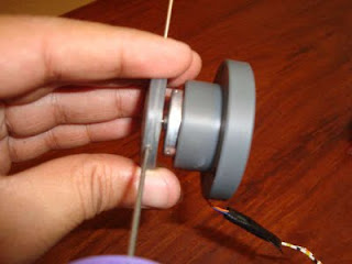
DIY Anemometer- Sensor for Laminar Flow Fountain Control at High wind

I have made a small wind sensor from a DC motor of old CD ROM. This DC Motor does generate 0.3V at high wind. So i have to use it for my Laminar Nozzle project. At low wind the voltage generated by the motor is little but if wind is on higher side a voltage of about 0.12 VDC the fountain stream can be disturbed.

Did a little programming in Arduino when a DC voltages reaches to 0.12Volts stop the fountain and when the voltage below this value ON the fountain... I know you people will understand.. this is not a real Anemometer but with wind it gives us a voltage reading which we can use to start or stop the fountain.

Saturday, June 11, 2011

Updates on Laminar Flow Nozzle

Dear readers,
Been involve in developing the garden in-front of my house. I am going to install laminar flow fountain their. I made this fountain from 6inch diameter 1foot length pipe. The stream seems to me a perfect laminar. you can see how crystal clear it is.
I have to install RGB lighting and cutter mechanism. A good micro-controller programming will reveal millions of colours in this fountain.

and here a small video clip. Actually the Nozzle is connected to low pressure tap water, therefore the laminar Arc is small. I have to make a small pond with pump that will give this fountain a real life.

Sunday, May 15, 2011

Graphical Waterfall- Last Video

Hi,
This is the last video i made this morning. I added color additives to the water but the camera did not catch the graphics in the waterfall :)...


I am currently involves in too many projects and i am abandoning it for the time being. Following is the micro-controller programming i did:


//Pin connected to ST_CP of 74HC595
int latchPin = 6;
//Pin connected to SH_CP of 74HC595
int clockPin = 13;
////Pin connected to DS of 74HC595
int dataPin = 11;
byte FirstByte;
byte SecondByte;
byte ThirdByte;
byte FourthByte;
byte FifthByte;
int val;
byte serialInArray[5]; // array for storing 5 bytes as they arrive from VB software
int serialCount = 0; // for counting the number of bytes received


void setup() {
  //Start Serial for debuging purposes 
  Serial.begin(9600);
  //set pins to output because they are addressed in the main loop
  pinMode(latchPin, OUTPUT);

}

void loop() {
  
   if (Serial.available() > 0){
       serialInArray[serialCount] = Serial.read(); // read a byte sent by processing
        serialCount++;  // increment number of bytes received

    if (serialCount > 4 ) {  
 FirstByte = serialInArray[0]; 
 SecondByte = serialInArray[1]; 
        ThirdByte = serialInArray[2];
        FourthByte = serialInArray[3];
        FifthByte = serialInArray[4];
Serial.print(FirstByte);
Serial.print(SecondByte);
Serial.print(ThirdByte);
Serial.print(FourthByte);
Serial.print(FifthByte);
Serial.println("");

     digitalWrite(latchPin, 0);
    shiftOut(dataPin, clockPin, FirstByte); 
             shiftOut(dataPin, clockPin, SecondByte);
                 shiftOut(dataPin, clockPin, ThirdByte);
                 shiftOut(dataPin, clockPin, FourthByte);  
       shiftOut(dataPin, clockPin, FifthByte);
     
   
    //return the latch pin high to signal chip that it 
    //no longer needs to listen for information
    digitalWrite(latchPin, 1);
 serialCount = 0;
 delay(20);
   }
}
}
void shiftOut(int myDataPin, int myClockPin, byte myDataOut) {
  // This shifts 8 bits out MSB first, 
  //on the rising edge of the clock,
  //clock idles low

//internal function setup
  int i=0;
  int pinState;
  pinMode(myClockPin, OUTPUT);
  pinMode(myDataPin, OUTPUT);

 //clear everything out just in case to
 //prepare shift register for bit shifting
  digitalWrite(myDataPin, 0);
  digitalWrite(myClockPin, 0);

  //for each bit in the byte myDataOut�
  //NOTICE THAT WE ARE COUNTING DOWN in our for loop
  //This means that 000001 or "1" will go through such
  //that it will be pin Q0 that lights. 
  for (i=7; i>=0; i--)  {
    digitalWrite(myClockPin, 0);

    //if the value passed to myDataOut and a bitmask result 
    // true then... so if we are at i=6 and our value is
    // %11010100 it would the code compares it to %01000000 
    // and proceeds to set pinState to 1.
    if ( myDataOut & (1<
      pinState= 1;
    }
    else { 
      pinState= 0;
    }

    //Sets the pin to HIGH or LOW depending on pinState
    digitalWrite(myDataPin, pinState);
    //register shifts bits on upstroke of clock pin  
    digitalWrite(myClockPin, 1);
    //zero the data pin after shift to prevent bleed through
    digitalWrite(myDataPin, 0);
  }

  //stop shifting
  digitalWrite(myClockPin, 0);
}

Saturday, May 14, 2011

The Graphical Waterfall- First testing

This is first test of graphical waterfall consist 40 solenoid valves. All the things working fine but the graphics are hardly visible due to:
1- I have long tubing downstream the solenoids...If small metallic nozzles directly connected to the solenoid i would have got good results.
2- The Height of the solenoid. The solenoid are installed at about 8feet height, i think to see the graphical effect it must be 20 feet or above.

Any comments to improve will be highly appreciated

Friday, May 13, 2011

Almost there

Did wiring of Solenoids, not that good but if all thing work i will organize the wiring..Tomorrow is D'Day...Hope a good news..

Friday, May 6, 2011

Installation of Hardware for Graphical Waterfall

At last i completed the wiring of Solenoids and made an RC circuit to inject high current for short duration to increase the response time of solenoid. The resistance is 47RJ 5Watt and the capacitors i used are 50V 100mFarad.

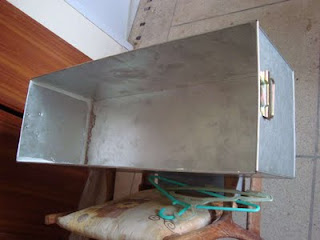
 and fabricated the sump from 24gauge galvanized sheet.
Tubing and wiring of solenoid..The most hectic work;)

just installed the Header at its place and the pump:)


Wednesday, April 20, 2011

Graphical Water fall- Single Solenoid valve testing with Water

I have added some videos on the Youtube. Actually i was testing a single solenoid valve and checking the response time.

The following video is a simple arrangement of solenoid without using RC .
and this one is with addition of Resistor 45.3 Ohm  and capacitor 50v 220mF.

Monday, April 4, 2011

Graphical Water fall- 1st Step to Reality

Moving toward the actual working of the Graphical waterfall:
UPDATES ON SOFTWARE:
I updated my Graphical programmer software:
1- A Loop checkbox and STOP button is added. If the 'Loop Checkbox' is ticked, the graphical hexadecimal data will be send to the micro-controller in a loop. So we will able to continuously run the graphical fountain and repeat the designs.
2- Pressing the Stop button will check how many bytes are in shift registers. Then the software will send numbers of  '0X00' to finalize the shiftout function. After shifting out the software will turnoff all the valves by sending 5-bytes '0X00' to the controller.


UPDATES ON HARDWARE:
1- Here are the 40 solenoid valves attached to the rig ...


 2- The completed Controller card.


Here is another video in sequence with the graphical waterfall LED simulator toward the actual controlling of single solenoid valve... You can hear the ON/OFF sound from the solenoid valve.
In the last few frames the solenoid stopped working and i just stumped what happen?..and after a little investigation found the +ve wire of solenoid detached..as i connected it temporirly with squash tape..smiley-wink

The positive thing of this test was:
1- My Connections of IRF540 good.
2- Solenoid response time is also good.
3- During the testing my circuit didn't get back emf from the solenoid as i have connected IN4007 across the solenoid. Thus my circuit is safe.
4- Testing one solenoid valve successfully gave me confidense that all the remaining 39 valves will work great.
5- I thought the LED of the tested solenoid valve will not be bright or will be off but it also work as usual.
6- The 74HC595 and micro-controller are as cold as in iceroom.

Here is the link of video:

Friday, March 25, 2011

Graphical Waterfall- Updates

Some advancements and updates on the software and hardware:

SOFTWARE Updates:
1- The software now can support all types of popular image format. Previously it only support WMF file Format.

2- Now you can add Colored images and then convert it in Pure Black and white.
3- Multuple image effects added, like Flip, Mirror and invert.
4- Delay Timer provided.
5- Scroll Bars were added to move big pictures inside picture container.


HARDWARE:
1- The PCB for controlling 40 solenoid valves was designed and etched.
2- The simulator was tested and a short video is in following youtube link:

3- Ordered more 30 solenoid valves. The pipe fittings are being machined on lathe. Hope i will be able to post some pictures in coming days.


and Here is the 6inch dia PVC pipe with 40 fittings for solenoid valves.

Saturday, March 19, 2011

DIY computer Controlled Graphical waterfall

Hi my Friends,
World is full of genius persons and i amazed to see how computer made life easier and how the ideas evolves and takes it shapes in real world...Long story short, sometime ago i saw a graphical fountain on You-tube:
http://www.youtube.com/watch?v=tnPnwET4x9k
Watching this video amazed me and convinced me to make a cheap but high quality version of the same... Looking at the fountain, it seems that water droplets are controlled through 100's of solenoid valves and each of the solenoid valve is controlled through computer in a complex manner and a complex programming...
So to make a computer controlled graphical fountain, we require:

1- A complex software that generate images into binary data and send to micro-controller.
2- Electronic hardware that plays as a bridge between Computer and Solenoid valves.
3- Mechanical structure that hold overhead reservoir with solenoid valves and a drain.

All above tasks are doable..... So i started making program and electronics hardware at the same time... when i tired from electronics i started programming... so eventually both the software and hardware completed at the same time..
The following picture of software shows how a number of solenoid valves can be operated in a manner to make beautiful stunning water effects....The Software is user freindly and designed to operate in following steps:
1- You have to select an image 'WMF' black and white

2- Select the number of solenoid valves you have installed on the fountain. The greater the number of valves the greater the resolution and beauty of fountain.

3-Convert this image into '1' and '0' i.e. binary data... If you check the 'Add each design to one file' checkbox..you will have different designs in a single file

4-Open the computer USB port at which the micro-controller is installed.

5-Press 'SEND' button and see the stunning effects..


 More explained:
1- The software convert the photograph in binary data. The Black color is '1' and the white color is '0'.
2- Considering 16 solenoid valves, will give you 16 values of '1' and '0'. these 16 values has to be considered as two bytes data.
3- my software then convert each row into hexadecimal to shorten the data.
4- this data is sent through USB serial port to the micro-controller.
5- Their is small adjustable delay between the two rows of data. this delay separate the drops of rows.
By electronic Hardware i mean the "Simulator", that consist of Microcontroller and LED's.. currently installed 16 LED's to mimic the Solenoid valves..
Here is the short video of working simulator:
http://www.youtube.com/watch?v=bGZjb0nHGJQ
I also purchased 16 solenoid valves too to start making the structure of the fountain.... I am here posting pictures of my software and its working...